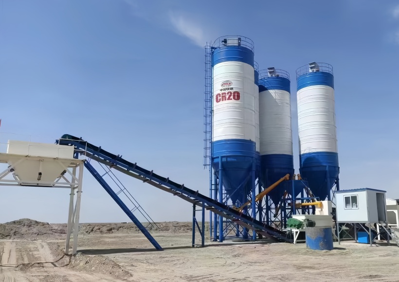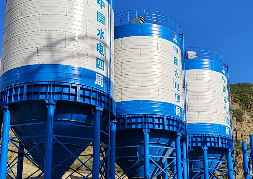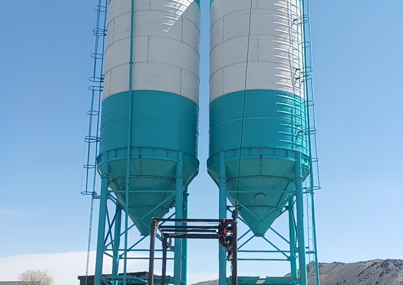









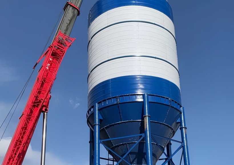
Walk onto any ready-mix plant or concrete batching terminal at 3:00 AM, and you will eventually hear it: the dull, metallic clang of a twelve-pound sledgehammer beating against a hopper cone. When a 100-ton bulk storage unit goes quiet, production halts. Operators do not care about textbook definitions of mass flow; they care about why their Type I Portland cement has locked up inside the cone again.
Managing dry bulk material handling requires dealing with real-world physics, not idealized scenarios. Cement powder, fly ash, and granulated blast furnace slag are highly cohesive, hygroscopic, and prone to severe compaction. Relying purely on the gravity-fed design of a standard silo structure is a recipe for operational failure. To secure a consistent discharge, you must understand how to properly integrate a cement silo aeration system that handles real-world ambient conditions, including high humidity and fluctuating pressure.
       [ Compacted Material Zone ]
             \               /
              \             /
               \           /
       [Arch]   =======   <-- Localized Compaction Interlocking
                 /       \
                /         \
               /           \
         [ Hopper Outlet ]
The Mechanical Anatomy of a Blocked Silo: Beyond the Brochure
The industry loves to talk about bridging and ratholing as if they are simple, distinct bullet points in a catalog. In the field, they are expensive nightmares caused by a combination of material properties and incorrect pneumatic setups.
Bridging and Localized Compaction
Bridging occurs when cement particles mechanically interlock and form a self-supporting arch across the hopper wall cross-section. This usually happens right above the transition zone where the vertical silo body meets the sloping cone.
What causes this arch? It is rarely just the raw weight of the powder. The true culprit is often extended static storage combined with moisture ingress. When a silo sits idle over a damp weekend, the moisture content in the air inside the silo causes localized hydration. The fine cement particles form weak chemical and physical bonds, drastically increasing the bulk material’s cohesive strength. Once that arch forms, the material flow stops entirely, leaving empty space above the discharge outlet while tens of tons of powder sit trapped above.
The Mechanics of Ratholing
Ratholing is an equally disruptive flow problem. It typically happens in silos designed for funnel flow, where the material discharges down a central vertical channel directly above the silo outlet.
The cohesive material along the interior silo walls remains completely stagnant. As the core empties, this stable vertical channel narrows. The powder on the sides compacts further under its own weight, eventually hardening into a semi-permanent structure. This significantly reduces the active storage capacity of your silo. If left unaddressed, that stagnant material can sit for months, absorbing ambient humidity, caking onto the steel plates, and creating structural eccentricities that can actually buckle the entire silo structure under uneven loads.
Fluidization Mechanics: Why Low-Pressure Air Fails in Humid Climates
To break these flow issues, plants look to pneumatic fluidization. However, simply pumping compressed air into a hopper cone without calculating the fluidization curve will only worsen your issues.
      [ Dry Air Supply Line ]
                │
         ┌──────┴──────┐
         ▼             ▼
   [ Air Pad 1 ]  [ Air Pad 2 ] ──> Creates Fluidized Frictionless Boundary Layer
         │             │
   ═════════════════════════════  <── Interior Silo Wall Surface
True fluidization introduces low-pressure air at a volume and velocity that spaces out the fine cement particles, reducing inter-particle friction and the friction between the powder and the hopper wall surface. This changes the material behavior from a cohesive solid to a pseudo-fluid that flows smoothly through the discharge outlet.
But here is where the cross-border supply chain and localized environmental factors bite you. If you are operating a concrete plant in a high-humidity environment—like the US Gulf Coast or Southeast Asia—your ambient air is saturated. If your maintenance crew skips draining the air compressor’s oil-water separator, or if your refrigerated air dryer fails, you are pumping hot, wet, oil-fouled air directly into the bottom of your dry cement mass.
When wet air hits the microscopic pores of a standard textile fabric aeration pad or air fluidizer, two things happen:
- The canvas or sintered polymer membrane becomes wet and contaminated with oil.
- Fine cement particles migrate backward during non-aeration cycles, mixing with that moisture right on the pad surface.
The cement hardens directly inside the membrane. This process, known as pneumatic blinding, renders the pad useless. The air pressure drops, fluidization stops, and the air compressor works harder while the air bypasses the blinded pads entirely, creating localized air channels that carve holes through the cement without moving the bulk mass.
Designing for Zero-Downtime: The Strategic Integration of System Components
To prevent these issues, engineering teams like those at Tongxin Mashine design bulk handling setups with precise air distribution and durable component materials. A reliable cement silo aeration system does not rely on a single type of device; it uses an organized layout tailored to the specific cone angle and the material handling rate of the plant.
   ┌────────────────────────────────────────────────────────┐
   │             Silo Fluidization Layout                   │
   ├────────────────────────────────────────────────────────┤
   │  [Upper Ring]   3-4 Air Nozzles (High-Velocity Bursts) │
   │                                                        │
   │  [Lower Ring]   4-8 Aeration Pads (Continuous Flow)    │
   └────────────────────────────────────────────────────────┘
Optimizing Aeration Pads and Air Pads
For standard continuous discharge, low-pressure aeration pads installed in a ring configuration around the lower third of the hopper cone are the industry standard. These pads need to introduce air pressure slightly higher than the head pressure of the material above them—typically between 3 to 15 PSI (0.2 to 1.0 Bar).
The air flow must be continuous during discharge cycles to maintain a frictionless boundary layer along the interior silo walls. If the air pressure is too high, it creates an air jet that blows straight through the material to the surface (channeling), leaving the rest of the material unfluidized. If it is too low, the weight of the cement seals the pad, preventing air distribution.
The Role of High-Pressure Flow Aids
When dealing with stubborn materials like fly ash, which has a higher propensity for ratholing due to its varying particle size and moisture retention, low-pressure fluidization pads might not be enough to break a hardened arch. This is where high-pressure air cannons or automated air nozzles come into play.
An air cannon does not fluidize; it delivers a short, high-pressure blast of compressed air (typically 70 to 100 PSI) directly into the dead zones of the hopper wall. This structural shockwave physically breaks the cohesive bond of the arch, causing the mass to collapse down into the fluidized zone created by the lower air pads.
However, you must be careful with timing. Running an air cannon when the discharge valve at the silo outlet is closed compresses the powder further, worsening the blockage. The pneumatic control circuit must link directly with the gate valve status.
Field Realities: Sledgehammers, Fabric Wear, and Sensor Failures
Experienced plant managers know that the greatest enemy of a good cement silo aeration system is often the operator’s lack of patience. When the batch controller flags an incomplete batch weight due to a slow cement discharge, the immediate reaction is to turn on every vibrator and send someone out with a sledgehammer.
Continuous vibration without active material discharge is highly damaging. Mechanical vibrators impart energy that shakes the steel silo wall, which can help dislodge material buildup. But if the slide gate is shut, that vibration simply packs the fine cement particles tighter, turning a loose bridge into a highly compacted block.
Furthermore, repeated sledgehammer blows deform the hopper wall, creating internal dents and localized flat spots. These imperfections act as ledges that give cohesive material a foothold to anchor a new arch, worsening the long-term flow issues.
     [ Sledgehammer Blow ] ──> Dents Hopper Wall
                                    │
                                    ▼
                       Creates Internal Metal Ledge
                                    │
                                    ▼
                    [ Catastrophic Arch Anchor Point ]
Another hidden vulnerability lies in the level sensors. When a silo experiences severe ratholing, the center core empties out while a thick ring of material clings to the walls. A standard top-mounted radar or ultrasonic level sensor pointing down the center will read the silo as nearly empty.
Based on this false data, logistics managers order another 30-ton pneumatic tanker delivery. When the truck hooks up and begins pumping cement powder into a silo that actually has 20 tons of stagnant material stuck to the sides, the silo overfills, blowing out the top dust collector membranes and creating an expensive environmental and structural hazard.
Maintaining system efficiency requires using high-quality bulk storage components from experienced manufacturers like Tongxin Mashine. This must be paired with an automated maintenance routine that includes verifying air supply dryness, inspecting level sensors, and regularly replacing worn aeration membranes before they blind or tear.
Technical Specifications for System Configuration
To assist engineering and procurement teams, the following layout guidelines outline the pneumatic and physical requirements for proper system configuration across different material profiles:
| Material Type | Typical Particle Size | Propensity for Bridging | Recommended Aeration Media | Required Operating Pressure |
| Type I/II Portland Cement | 10 to 45 microns | Kati hadi juu | Sintered Polymer / Heavy Duty Canvas Pads | 5 – 12 PSI (0.35 – 0.85 Bar) |
| Class F / C Fly Ash | 5 to 30 microns | High (Moisture Sensitive) | Sintered Stainless Steel / Silicon Nozzles | 8 – 15 PSI (0.55 – 1.0 Bar) + Air Cannons |
| Ground Slag (GGBS) | 5 to 20 microns | Very High (Cohesive) | High-Density Fluidizer Pads with Edge Seals | 10 – 18 PSI (0.70 – 1.25 Bar) |
Note: Air volume consumption must be calculated based on the total surface area of the active fluidizing zone. A general rule of thumb for standard Portland cement is to supply 6 to 10 CFM of dry air per square foot of active fluidization pad area.
Maswali Yanayoulizwa Mara kwa Mara
1. How can I tell if my aeration pads are blinded without opening the silo?
Go stand right next to the pressure gauge on your fluidization air manifold while the silo gate is open and discharging. If your line pressure normally runs at a steady 7 or 8 PSI but suddenly pegs at 18 or 20 PSI while your actual cement discharge slowed to a pathetic trickle, you have a problem. That high pressure tells you your air is hitting an absolute brick wall. The fabric or polymer porous material is completely scaled over with a hardened crust of cement. If you happen to have a CFM flow meter inline, you will see the exact opposite—the air flow rate will drop down near zero. High pressure plus zero flow equals blinded membranes. Period.
2. Can I use an aeration system if my silo is designed for funnel flow?
Sure, you can bolt them onto the cone, but don’t expect miracles. Funnel flow silos are fundamentally flawed for sticky, fine materials because the center drops out while the sides stay dead still. Shoving air pads into a shallow 45-degree funnel cone won’t magically transform it into a clean, uniform mass flow system. What it actually does is slightly broaden that central chimney flow zone so your rathole does not pinch shut quite as fast. If you are stuck dealing with a terrible silo design inherited from a cheap contractor, use a staggered ring of fluidizer discs to force the material boundary layers to shear off. It is a temporary band-aid, not a structural cure.
3. Why did my hopper cone start cracking near the fluidizer mounts?
Because somebody welded a mount or a vibrating bracket straight to a thin-gauge sheet metal wall without a reinforcement pad, or your operators are running the vibrators continuously when the bottom slide gate is shut. When you vibrate a dead, static column of cement, that energy cannot move the material—it has nowhere to go. So, it flexes the steel plates back and forth until the metal fatigues and splits right along the heat-affected zone of your welds. Never attach vibration flow aids or heavy fluidizer ports onto bare silo skin. You need a heavy doubler backing plate to spread that localized mechanical stress out, and you must interlock the vibrator controls so they can only fire when the gate valve is 100 percent open.
4. What is the maximum distance an air cannon can reach inside a compacted cement silo?
In the real world, a standard 4-inch air cannon blasting at 90 PSI gives you an honest, effective smash radius of about 4 to 6 feet through packed powder. Disregard those theoretical OEM catalog charts claiming a single blaster can clear an entire 15-foot wide zone. Fine dry powders absorb blast energy like a giant sponge. If you are dealing with a massive 20-foot terminal silo, one lone cannon will just punch a tiny, localized mouse-hole straight through the bridge without dropping the main mass. To actually drop a massive blockage, you have to stagger multiple cannon nozzles in a spiral pattern ascending the cone, then fire them sequentially from the bottom up to peel the crust off the walls.
5. How does temperature variation between day and night affect fluidization?
It turns the upper section of your bulk storage into a giant condensation pump. On a baking hot afternoon, the air inside the silo’s empty headspace expands and drinks up a massive amount of ambient humidity. When night hits and the outside temperature plunges, that external steel shell cools down in minutes. That hot, humid internal air slaps against the freezing steel wall, condenses into raw water droplets, and runs straight down into your dry cement border. This creates a thick, pasty, half-hydrated crust right around the top internal perimeter of your hopper cone. When that heavy crust eventually snaps off and slides down into the throat, it acts like a giant blanket that seals off your air pads, causing total system failure.