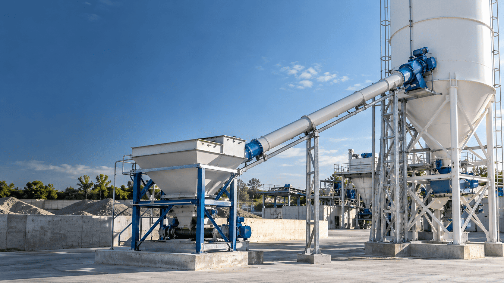

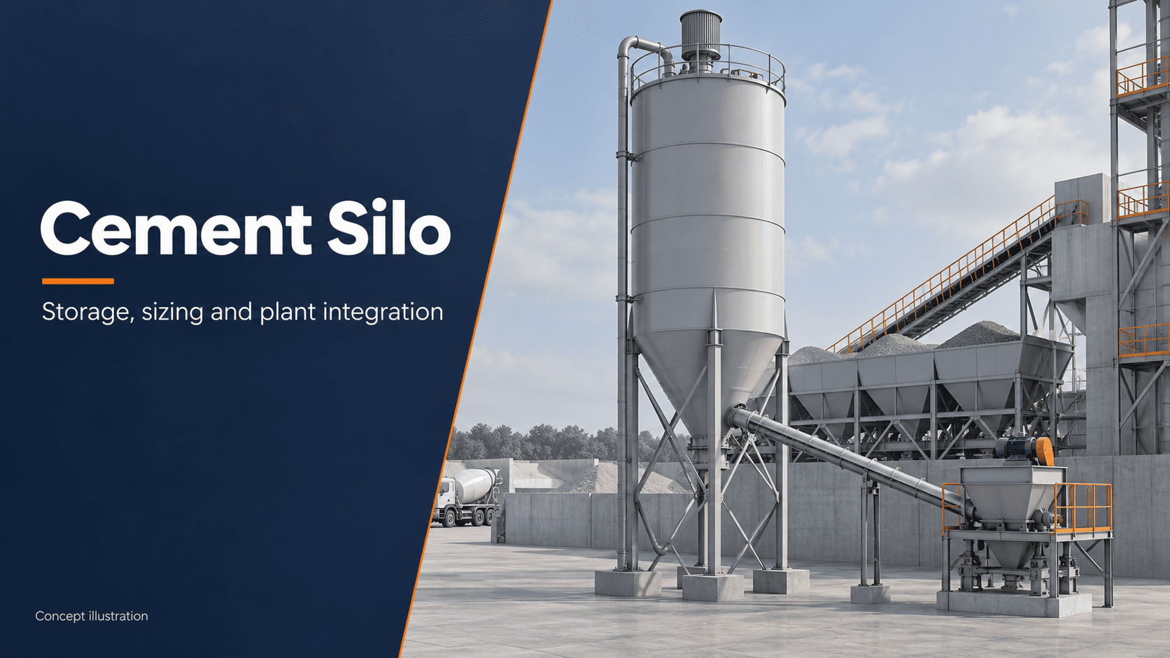
A cement silo is a storage vessel for dry cement powder. It receives cement in bulk or from bags, protects the stored material through an enclosed storage arrangement, and supplies it to a mixer, weigh hopper or other production equipment. In a concrete plant, the silo holds one of the ingredients used to make concrete; it does not normally store fresh concrete.
The vessel is only part of the system. Powder has to enter without escaping into the surrounding area, conveying air has to leave, and stored material has to reach the receiving equipment at the required rate. Shell construction, hopper geometry, dust filtration, discharge equipment and controls determine how that process works.
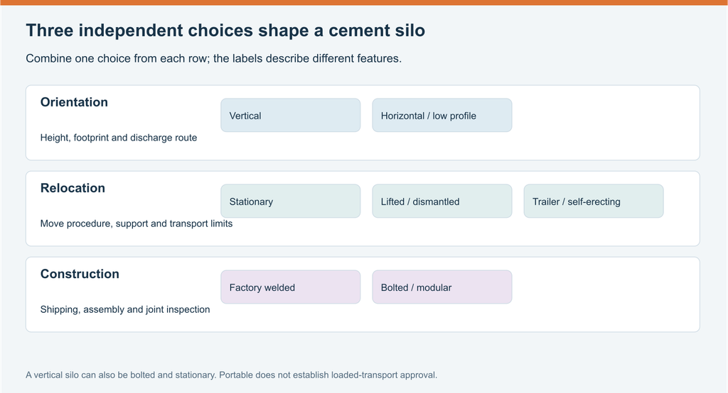
Different projects put different demands on storage. A permanent ready-mix plant may favor a vertical installation with substantial reserve stock. A site with restricted height may use low-profile storage. A contractor moving between projects may need a portable unit, while an installation shipped over a long distance may benefit from bolted construction. These features can overlap: a silo can be vertical, bolted and stationary at the same time.
This guide explains the working principle, main parts, types and applications before turning to capacity, transport and cost. TXMixing’s cement silo range provides a starting point for the product discussion; the following explanations show what the different configurations change in operation.
What a Cement Silo Stores and Where It Fits
Cement is a fine powder used as a binder in concrete. At a batching plant, it remains separate from aggregates and water until the production process brings the ingredients together. The silo provides a reservoir between intermittent material deliveries and repeated concrete batches, so the plant does not have to receive cement every time it mixes a batch.
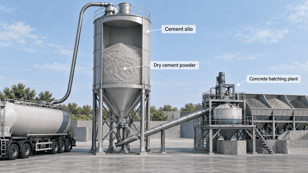
Bulk storage can reduce routine bag handling and make repeated dosing easier to integrate with the plant. Whether it lowers overall costs depends on delivered material prices, consumption, equipment and operating arrangements. A silo creates the opportunity for bulk supply; it does not guarantee a saving for every project.
The storage system may also be configured for another dry powder, such as fly ash or ground slag. That possibility depends on the material and the equipment. Differences in bulk density, flow behavior and production routing affect storage and discharge. A capacity stated for cement cannot automatically be reused for another powder, and a shared vessel is not a substitute for separate storage where a recipe requires distinct materials.
The phrase “concrete silo” can refer to a tower constructed from concrete rather than equipment that stores cement. Grain bins, silage towers and bunkers have their own uses and handling arrangements. For concrete production, the relevant question is how a dry cementitious powder is received, stored, measured and conveyed.
The receiving plant determines the final part of the route. A weighed concrete batching plant normally measures cement in a receiving weigh hopper before mixing. A volumetric production system uses a different feeding and proportioning arrangement. A transfer installation may move powder to another vessel. Those uses share a storage function but do not have identical discharge and control requirements.
Keeping materials identifiable is part of the storage arrangement. Where several powders are used, fill connections and discharge routes need clear assignment. Delivery records, material identifiers and stock records let operators connect an incoming load to the material later used in production. That traceability is useful during normal supply and when a quality or inventory discrepancy is investigated.
Bulk delivery, bags and the value of a storage buffer
A bulk tanker fills through a pneumatic connection, while bagged supply needs a different receiving arrangement. Small bags may be emptied through purpose-designed handling equipment; larger bulk bags can use an unloading station connected to a conveyor. A bag unloader and a tanker fill pipe are different interfaces, even if both ultimately supply the same powder-storage process. The receiving method should be defined before the silo package is priced.
Bulk storage separates delivery events from individual production batches. This can reduce repeated bag handling and packaging disposal, while allowing a larger quantity to be received at once. The benefit is strongest where consumption is regular and bulk delivery is practical. Low or intermittent demand may not justify the additional equipment, and a site without suitable tanker access may need a different supply method. A silo improves supply flexibility when it fits the operation; it does not remove delivery lead time or make production independent of material supply.
Moisture protection and storage duration
Cement needs protection from water before it is mixed intentionally. The American Cement Association explains that portland cement absorbs moisture. Weather protection is therefore a material-quality requirement as well as a housekeeping concern. The roof, access closures and fill connections form part of that enclosure, while the vent remains a necessary, controlled air path.
There is no useful universal answer to how long cement can remain in a silo. The cement supplier’s requirements, material condition, exposure and stock turnover matter. A larger reserve can provide delivery resilience but may also lengthen the time some stock remains in storage. Delivery and consumption records help identify slow-moving inventory. When moisture exposure or material condition is in doubt, assessment against the supplier’s acceptance requirements is more useful than assuming that an enclosed vessel preserves cement indefinitely.
Cement Silo Working Principle: Filling, Storage and Discharge
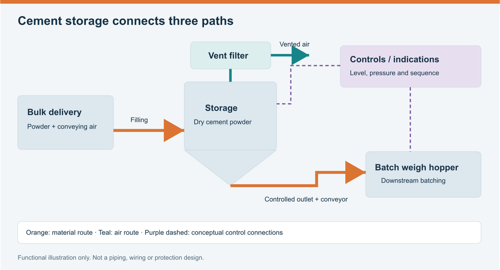
The working principle follows a material route from receipt to production. During pneumatic delivery, a tanker or transfer system moves cement through a filling line with conveying air. The powder enters the vessel, separates from much of that air, and joins the stored inventory. The air exits through the venting arrangement, while the filter captures entrained dust.
Filling and the movement of air
A filling pipe provides the path into the storage vessel. Its connection, route and support arrangement belong to the delivery interface. As powder enters, the receiving system has to handle both the volume of incoming material and the air used to convey it. Treating filling as a powder-only process misses a central part of the operating principle.
A vent filter passes air through filter media while retaining dust. In a reverse-jet system, cleaning pulses remove captured powder from the elements so that it can return to the vessel. WAM’s SILOTOP zero technical catalogue, issue A, January 2017 describes this function for that product. Its utility and operating requirements apply to the specified filter, rather than establishing universal values for all storage equipment.
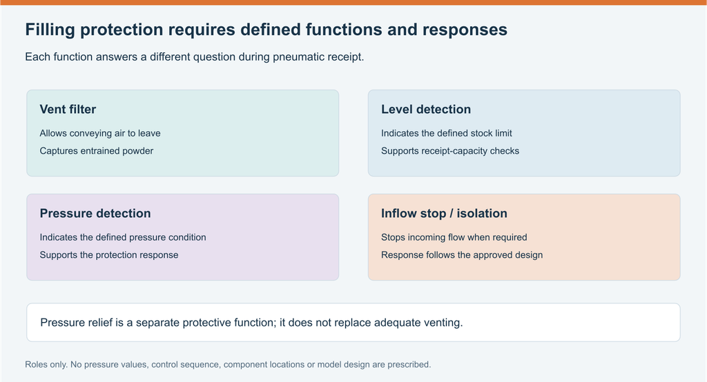
Pressure can rise if air enters faster than it can leave. Hycontrol’s silo-protection explanation identifies restricted venting and excessive incoming airflow as possible causes. It also explains why ordinary storage vessels should not be assumed to carry a pressure-vessel rating. Venting, pressure relief and stopping inflow therefore have distinct roles in a filling system.
Storage and movement toward the outlet
The shell contains the powder and the hopper directs it toward the discharge opening. Stored powder does not behave like water in a tank. Its movement depends on the material, contact surfaces, storage conditions and outlet geometry. Material can remain in parts of a vessel while the active flow path supplies the outlet; a visible or measured inventory does not always mean that all of it is readily available to production.
Flow aids can support discharge where the selected arrangement requires them. Aeration introduces controlled air near the outlet, while mechanical devices act through a different method. The appropriate equipment and sequence depend on the powder and vessel design. Adding more air or vibration indiscriminately can change the process without resolving the cause of poor flow.
An outlet valve or other discharge device controls material leaving storage. In a screw-fed arrangement, the rotating screw transports powder along its housing to the receiver. The screw’s installed route, available material at the inlet and operating sequence influence the delivered rate. The vessel, outlet and conveyor should be understood as one material path.
Bridging, rat-holing and compaction
Poor discharge can take different forms. Bridging is an arch of material above an outlet that interrupts flow. Rat-holing occurs when a narrow channel empties while surrounding powder remains in place. Compaction is the packing of stored powder into a denser condition. These distinctions explain why a vessel can still contain material while its outlet supplies little or none. BinMaster’s flow-aid explanation describes these mechanisms and the roles of aeration and combined flow aids.
Aeration pads introduce air near selected regions; a vibrator applies mechanical movement. They act differently and may be combined in an engineered arrangement. Neither is a substitute for matching powder characteristics, hopper geometry and outlet duty. Diagnosing the flow condition comes before changing the equipment or operating sequence. A stopped outlet, a restricted conveyor and a misleading inventory indication can produce similar production symptoms without having the same cause.
Conveying, weighing and the production cycle
For weighed batching, the conveyor supplies a cement weigh hopper. The hopper measures the quantity needed for a batch, then discharges it into the mixing sequence. A conveyor moves material; the weighing arrangement establishes the batch quantity. Keeping those functions separate explains why increasing conveyor speed does not, on its own, improve measurement accuracy.
The control system coordinates the route. It can use material selection, instrument states, alarms and production commands to manage filling and feeding according to the approved sequence. A level indication describes a storage condition, while a batch weight describes a production charge. Both may appear on an operator display but answer different questions.
A complete system also includes the receiver’s behavior. Incoming powder displaces air there too, and the receiving hopper must have suitable capacity, venting and discharge arrangements. WAM’s ES/ESV manual, issue A11, September 2016 includes the weigh-hopper vent in its fault assessment. This illustrates why a slow-feed problem should be traced through the downstream equipment as well as the storage outlet.
Key Components of a Cement Silo
A cement silo combines a storage vessel with equipment for filling, venting and discharge. The components below explain how it receives powder, holds stock and supplies production. Some are mounted on the silo; others, such as a compressor or receiving weigh hopper, may be separate parts of the plant. The supplied package determines which items are included.
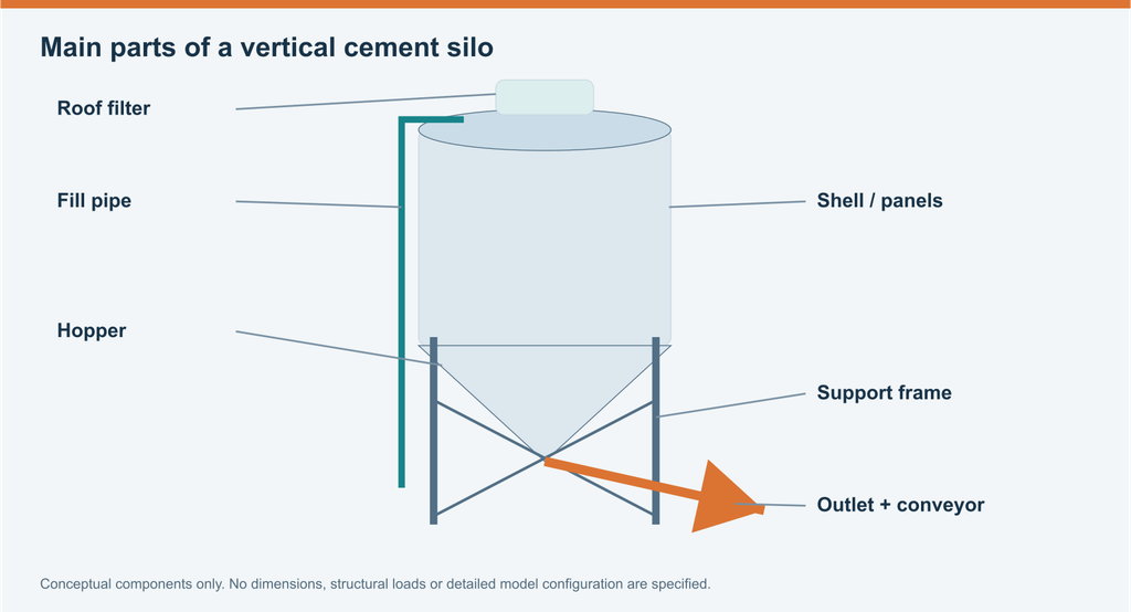
Silo Body and Roof
The silo body forms the main storage enclosure. In a typical vertical steel silo, a cylindrical shell holds the powder above the discharge hopper. The roof closes the top and provides connections or mounting positions for equipment such as the fill arrangement and vent filter.
The enclosure keeps powder contained and protects it from unwanted moisture ingress. Joints, openings and seals form part of that protection. During pneumatic filling, however, conveying air must leave through a controlled vent. An enclosed cement silo is therefore different from a vessel with no air outlet.
Hopper or Discharge Cone
The hopper is the lower section that brings stored powder toward the outlet. A vertical silo often uses a conical hopper, while other layouts can have a different shape or several discharge regions. Its geometry and outlet arrangement influence how material reaches the feeder.
Powder does not drain like water. Material properties, contact surfaces and the hopper design affect discharge, which is why the cone may be fitted with aeration or another selected flow aid. A steep cone alone does not establish how completely or consistently the material will flow.
Support Frame and Legs
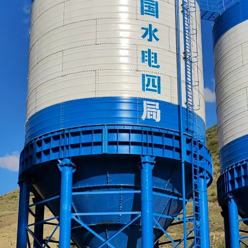
The support frame, legs and bracing hold the vessel in its operating position and transfer the equipment and stored-material loads to the supporting surface. An elevated frame also creates space for the outlet and conveyor connection below the hopper.
The supports belong to the complete structural arrangement, together with their connections and the foundation or other approved operating support. Transport wheels, where fitted, may serve a different purpose from the supports that carry a filled vessel during production.
Fill Pipe and Delivery Connection
The fill pipe carries incoming cement from the delivery connection into the storage vessel. In a pneumatic arrangement, cement and conveying air travel together along this route. The connection allows the tanker or transfer system to supply the assigned silo.
In a multi-silo installation, each fill connection needs a clear material and destination identity. The pipe route and its supports also have to fit the delivery position. Bag-fed storage uses a different receiving interface, such as a designated bag-unloading arrangement, rather than automatically using the tanker connection.
Dust Collector or Vent Filter
A cement silo dust collector captures powder carried by the air leaving the vessel during filling. The filter allows air to pass through its media while retaining entrained particles. This provides a defined air exit and reduces powder escaping with the exhaust air.
The assembly includes filter elements, a housing and its cleaning arrangement. A reverse-jet filter uses cleaning pulses to dislodge collected powder; other designs have their own cleaning requirements. Filter condition and adequate venting matter during receipt. A dust collector is not a replacement for the silo’s separately specified pressure-protection equipment.
Level Indicators and Stock Measurement
Level indicators tell operators about the material level inside the silo. A point switch reports when powder reaches a defined location; a continuous instrument estimates level over a range. High-level detection can form part of the filling protection, while other indications support inventory planning.
Load cells, when included in a suitable weighing arrangement, assess stored mass. Level and mass are different measurements, and neither is automatically the same as the cement weight measured for an individual production batch. The receiving weigh hopper performs that separate batching function.
Pressure Monitoring and Relief Equipment
Pressure monitoring identifies a pressure condition inside the vessel. In the approved protection system, its signal may initiate an alarm or stop incoming material. A pressure-relief device performs a separate protective function under its specified operating conditions.
These components work alongside the vent filter and level protection. A clear air outlet, a high-level response and a pressure response address different conditions during filling. Their limits and operating sequence are set for the selected system rather than inferred from nominal storage capacity.
Aeration Pads
Aeration pads introduce controlled air into selected regions near the hopper outlet to help fine powder move toward discharge. They can support flow where powder settles or compacts, allowing the outlet to supply the conveyor more consistently.
Their position, air supply and operating sequence depend on the vessel and material. Aeration is a flow aid, rather than a way to turn any hopper into a suitable design for every powder. TXMixing’s cement silo aeration guide explains its role in the discharge process.
Vibrators and Other Mechanical Flow Aids
A vibrator applies mechanical movement to assist material release in the selected discharge arrangement. It acts differently from an aeration pad, which introduces air. Some systems use one method; others combine flow aids according to the material and equipment design.
These devices support the outlet’s operation but do not replace suitable hopper geometry or a functioning conveyor. Persistent discharge problems need their cause identified before the installed settings or equipment are changed.
Screw Conveyor or Auger
A screw conveyor moves cement from the silo outlet to a receiving hopper, mixer or other process connection. A rotating flight inside a tube or trough carries material along the conveyor. Its drive supplies the motion, while the inlet receives powder from the discharge assembly.
The installed length, inclination, material and inlet conditions affect its duty. The conveyor transports powder; the downstream weighing system determines the charge in a weighed batch. TXMixing’s screw conveyor range is the relevant product reference for this part of the material route.
Outlet Valve
The outlet valve controls or isolates the connection between storage and the discharge equipment, according to the selected design. It can help manage the material route during operation or an authorized service task. Its location and function should be read together with the feeder and plant sequence.
A valve is not automatically a precise batching device. In a screw-fed weighing arrangement, the outlet, conveyor and receiver perform distinct jobs that must be coordinated.
Air Compressor and Conveying Blower
A compressor can supply pulse-filter cleaning, pneumatic actuators or the specified aeration system. It may be dedicated to the silo or shared with other plant equipment. Required pressure, airflow and air quality come from the connected devices’ documentation.
The conveying blower serves a different duty: moving powder along the pneumatic delivery route. That air may come from the tanker or a separate transfer system. A silo receiving pneumatic deliveries does not necessarily include an onboard compressor or blower; the actual package and utility connections define the arrangement.
Access Equipment and Controls
Ladders, platforms and access openings provide the physical access needed for specified inspection and service tasks. A manhole gives access to the enclosure, but entering the vessel remains a separately authorized maintenance activity rather than normal operation.
Controls coordinate the installed instruments, alarms, actuators and production commands. They connect component functions into an operating sequence so that filling, storage indications and feeding serve the intended process. Their scope may range from local equipment control to integration with an existing batching plant.
Cement Silo Types: Structure, Operation and Applications
The right cement silo depends on where concrete is produced, how often the equipment moves, the space available and the way it reaches the site. The common options below solve different practical problems. Their features can overlap: a stationary silo, for example, can be vertical and bolted.
Mobile Cement Silos
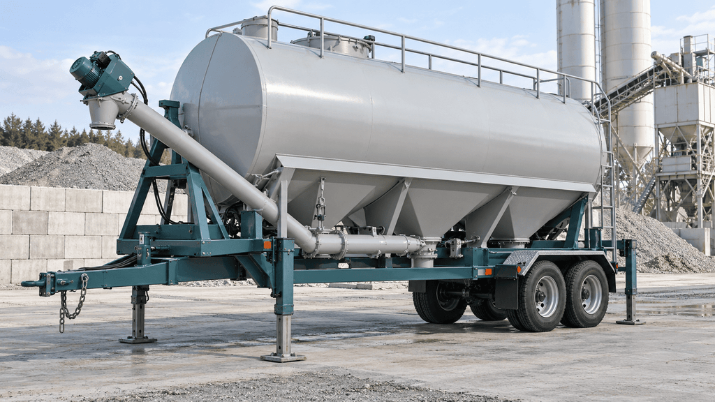
Mobile and portable cement silos provide cement storage for production that moves between sites. They suit contractors running temporary batching plants, infrastructure projects and remote jobs. Depending on the model, the unit may travel on a trailer, be lifted into place or use an erection mechanism to change between transport and operating positions.
The useful feature is the ability to support production at successive locations without procuring a new permanent storage installation each time. Temporary batching, infrastructure projects and contractors working across sites can benefit from that flexibility. The value depends on how often the equipment moves and how much work each move requires.
Some units combine storage, discharge equipment and transport features in one package. That can reduce the number of separate assemblies handled during relocation, but the complete operating arrangement still includes the receiving equipment, material deliveries and utilities. A quick erection mechanism does not eliminate every site task.
The distinction between transport and operation is particularly important. Zimmerman’s portable silo information states that its round and low-profile trailer units must be emptied before moving because their axles are rated for the empty equipment. This is a specific example of why loaded movement cannot be inferred from the presence of wheels.
Operating support can differ from the transport chassis. A filled unit may require the model’s specified supports or prepared operating surface rather than carrying its load solely on transport axles. Ground conditions, supports and the planned deployment remain part of the configuration.
Portability is less valuable when a vessel will remain at one site for most of its life. In that case, dedicated permanent storage and the associated plant layout may deserve priority. The portable option earns its cost when relocation solves a recurring operating problem, not merely because a project is described as temporary.
Stationary Cement Silos
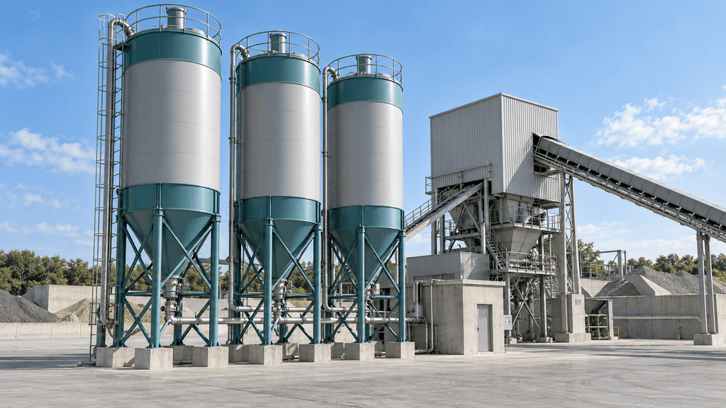
Stationary cement silos remain at a production site and supply a fixed batching or mixing system. They suit ready-mix plants, precast factories and other facilities with continuing material demand. A plant may use one vessel or several connected silos, depending on the materials and storage required. The installation is arranged around continuing production, with fixed supports, access, fill connections and conveying routes.
A multi-silo bank can separate cement grades and supplementary cementitious materials instead of combining all required stock in one vessel. Its capacity is assigned by material and supply schedule. More total storage is not helpful if the needed material is in the wrong vessel or the receiver cannot select it correctly. Each fill connection and production route needs a clear identity.
Expansion also changes the installation beyond the additional shell. Space for another support zone, delivery access, receiver connections and control functions may be required. An extra silo adds storage flexibility; it does not automatically provide redundancy if every vessel depends on one conveyor, utility or receiving hopper. The plant layout determines which interruptions additional storage can actually absorb.
Horizontal and Low-Profile Cement Silos
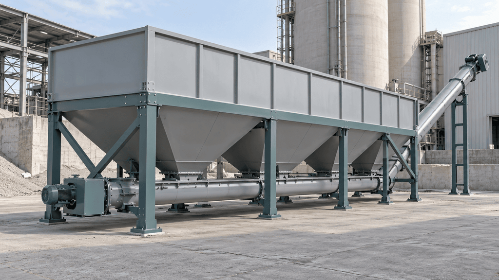
Horizontal cement silos spread storage along the ground rather than concentrating it in a tall tower. Low-profile designs also reduce overall height, although their vessel shapes vary. These options suit sites where overhead restrictions make a tall silo difficult to accommodate. Depending on the design, it may have one or several discharge regions and a conveying arrangement that gathers powder and carries it toward the receiving equipment. Low profile addresses an overhead-space problem; it does not describe one universal internal geometry.
The lower vessel can suit sites with restricted height or temporary layouts where an upright installation is inconvenient. Service access may be closer to ground level, although the actual filter, outlet and conveyor locations determine how accessible individual components are. The final conveyor still has to reach the receiver, so the highest part of the complete system may not be the vessel itself.
The main spatial trade-off is ground length. The body, supports and discharge equipment occupy a different envelope from an upright silo. A low unit installed beside a traffic lane can create a layout conflict that a taller, more compact vessel might avoid. Available height and ground area should therefore be considered together.
Some low-profile models are portable, while others operate as fixed installations. A lower centerline or the presence of wheels is not evidence that the equipment may travel while loaded. The selected model determines the operating support and transport state.
This type is useful when the height problem is real and the surrounding layout can accommodate the longer arrangement. It should not be selected solely because “horizontal” sounds easier to install; its discharge route and support requirements remain part of the project.
Vertical Cement Silos
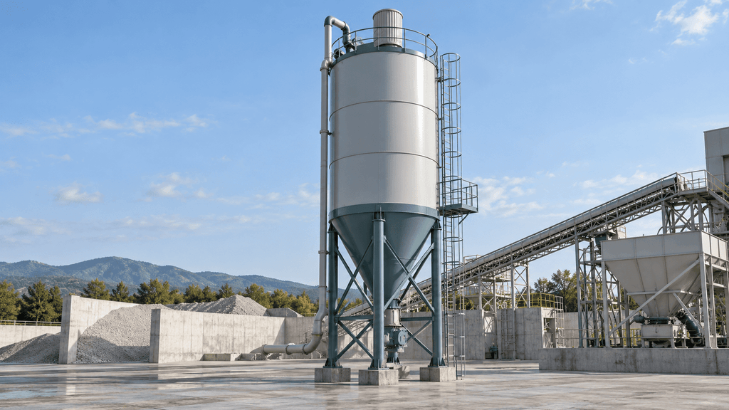
A vertical cement silo stores much of its inventory above the hopper in an upright vessel. This arrangement concentrates storage above a relatively compact ground area and allows the hopper to discharge from an elevated position. It is common in permanent concrete-production layouts where there is enough height for the vessel, filter and access equipment.
The elevated outlet can create a useful starting point for a conveyor route to the receiving hopper. The complete arrangement still includes supports, the conveyor and its connections, tanker access and service space. A small vessel footprint does not mean that the entire operating system occupies equally little ground area.
Vertical storage suits sites where available height can be used more readily than ground length. Ready-mix and precast facilities often consider it for fixed production, including installations with several separate powder silos. Expanding the storage bank can retain distinct materials and connect them to the required production routes.
Height creates the principal trade-off. Roof equipment and access can be above the vessel’s stated shell height, and installation or component replacement may require lifting resources. Where overhead structures or project constraints restrict the available envelope, a vertical layout may be impractical even when its nominal capacity is suitable.
A vertical silo can be welded or bolted. The orientation does not settle the shipping method, assembly work or joint system. Those construction choices should be considered separately from the benefit of using height to save ground area.
Bolted Cement Silos
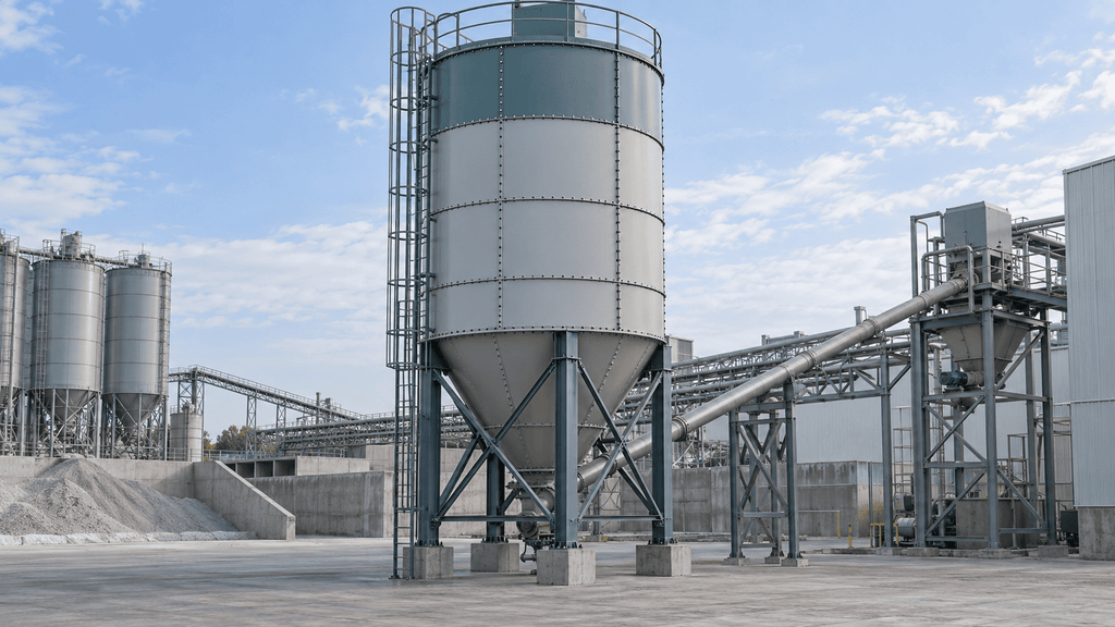
Bolted cement silos are supplied in panels or sections that are joined on site using bolts and a specified sealing system. Often described as bolt-together or modular silos, they suit projects where shipping an assembled vessel would be difficult or expensive. Modular describes sectional assembly; the connection method still needs to be stated in the proposed design. The modular arrangement allows the vessel to be shipped in a more compact form than the corresponding assembled body. At the destination, the sections become the completed enclosure through the approved assembly process.
This construction addresses a transport and installation problem rather than changing the fundamental storage task. It can be useful for long-distance delivery, containerized shipments where the proposed packing arrangement permits them, and sites whose transport routes cannot accommodate the assembled vessel.
Assembly introduces its own requirements. Panel identification, joint preparation, sealing materials, fasteners, access, lifting and inspection affect the result. Bolts provide a mechanical connection; the specified joint system provides the intended sealing performance. Neither can be replaced by a generic instruction to “tighten all bolts as much as possible.”
The modular arrangement may also support disassembly for a planned relocation, subject to the model, component condition and reassembly requirements. It is still different from a trailer-mounted unit intended for repeated moves. Dismantling, packaging, transport and rebuilding take resources even when the vessel is described as relocatable.
The main economic advantage appears when reduced shipping difficulty outweighs the extra assembly and inspection work. That balance changes with the destination, available labor and project scope. The bolted-versus-welded comparison explores this trade-off, while TXMixing’s modular cement silo information is the relevant product starting point.
The modular assembly guide helps explain the installation sequence. The actual model’s issued instructions determine joint details and inspection requirements. A modular vessel’s performance comes from the assembled design and execution, not the label alone.
Welded Cement Silos
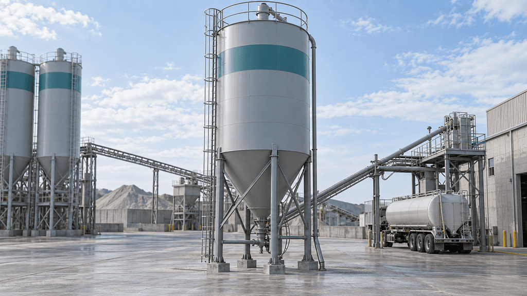
A welded cement silo uses welded shell connections and is often delivered as an assembled vessel or substantial assembled sections, depending on size and design. Much of the shell fabrication is completed before shipment. Site work then focuses on placement, supports, connections and the remaining equipment rather than assembling numerous shell panels.
That manufacturing arrangement can simplify the site’s shell-assembly task. It may suit projects with an accessible delivery route and lifting resources for the shipping dimensions. A vessel completed at the factory can also be inspected as an assembled enclosure before dispatch, according to the agreed inspection scope.
The transport envelope is the practical limitation. The empty vessel may occupy substantial cargo space despite carrying little material during delivery. Height, width, weight, route restrictions and unloading arrangements can dominate the project when the assembled vessel is difficult to move to its destination.
Welded construction is not proof of perfect sealing or an unlimited service life. The quality of welds, coatings, openings and attachments matters, as do the operating environment and maintenance. Nor does welded construction establish one capacity range for the entire industry; manufacturers use different product and shipping arrangements.
A welded option is attractive when factory assembly reduces meaningful site work and transport remains manageable. Comparing only the shell price overlooks the circumstances that make this advantage useful.
| Silo option | Principal benefit | Main limitation or trade-off | Typical application |
| Vertical | Uses height to concentrate storage | Overhead envelope, elevated service and lifting | Fixed ready-mix and precast production |
| Horizontal / low profile | Addresses restricted height | Longer ground layout and a different discharge route | Height-limited or temporary sites |
| Welded | More shell fabrication completed before shipment | Assembled shipping envelope and lifting | Projects with a manageable transport route |
| Bolted | Compact transport through sectional construction | Site assembly, sealing and inspection work | Long-distance delivery and modular installations |
| Stationary | Fixed plant integration and dedicated material routes | Permanent support and expansion interfaces | Established production facilities |
| Mobile / portable | Supports relocation between sites | Emptying, support, move and recommissioning requirements | Repeated temporary production projects |
| Cement pig / transfer vessel | Provides a different bulk-transfer role | Pressure design and downstream transfer compatibility | Reserve and transfer installations |
These descriptions help narrow the configuration: mobility for repeated moves, a lower layout for restricted height, vertical storage for a compact footprint, and a construction method that suits delivery and installation. Compare combinations that fit the project rather than treating each label as an exclusive choice.
Related Bulk Storage Equipment: Cement Pigs
A cement pig generally serves a bulk-storage and transfer role rather than simply duplicating an upright silo feeding a batch hopper. The exact configuration may use pressure-rated pneumatic discharge to move powder to another vessel or process. Its capacity, operating pressure, transport state and transfer equipment need to be understood as a separate design.
DSS’s Guppy 4200 product page describes a pressure-discharge configuration. That illustrates a different transfer role; it does not provide a pressure rating for an ordinary vented storage silo. A complete comparison follows where the powder goes next and how it is moved.
Such equipment can be useful where larger reserve storage supplies another receiving installation. It may also be part of a portable supply arrangement, depending on the model. The storage volume alone does not reveal whether it can feed the intended receiver directly or whether intermediate equipment is required.
A buyer comparing a cement pig with a conventional silo is comparing material-supply architectures as well as vessels. The relevant differences include pneumatic transfer equipment, available utilities, receipt and discharge sequence, support and transport conditions, and the role of the downstream storage or batching system.
Cement Silo Applications and Industry Environments
The storage principle is shared across several industries, but the required configuration changes with the production process. Concrete batching is the clearest example: deliveries add bulk inventory, conveyors feed the receiving system, and production consumes cement in repeated charges.
In ready-mix production, the storage bank supports concrete dispatch across a changing daily schedule. Capacity and delivery timing matter because demand can rise around large pours or additional shifts. Where several cementitious materials are used, dedicated storage and correctly assigned routes support the plant’s recipes.
Precast production connects storage to planned product batches and quality requirements. Different products may use different mixtures, so the material record and proportioning system are important alongside the total tonnage. A larger vessel does not replace the need to keep powders separate where the process requires it.
On-site concrete production brings supply closer to the work but adds site-specific constraints. The plant may operate for one project, access routes may change, and utilities or overhead space may be limited. A portable or low-profile configuration can address some of those conditions. The useful configuration is the one that serves the actual project sequence, including later removal.
Dry-mix mortar and other powder-processing installations also use silo storage, but their material flow, dosing and production equipment differ from a concrete batching plant. A cement-compatible vessel may form part of the storage arrangement; the complete feeding and measuring system needs to suit the process and other ingredients.
Grouting, soil stabilization and related construction processes can require controlled cement supply to specialized mixing equipment. Their production may follow a different duty cycle from ready-mix batching. The stored material, batch or continuous demand, transfer route and location determine whether a conventional storage silo or a different supply arrangement is appropriate.
Mining applications can also use cement as a binder in backfill production. In this setting, the storage system supplies cement to the mixing process rather than serving as a general-purpose container for mined materials. CMQ’s paste-backfill plant description identifies cement within that production arrangement. Binder demand, dosing and delivery logistics must be matched to the backfill process. This application does not imply that a cement silo is suitable for coal, ore, grain or every material used at a mine.
Industry environment also affects the package. Outdoor exposure makes enclosure, coatings, utility arrangements and access relevant. A coastal or corrosive environment may call for a different protection specification from a sheltered installation. That decision should be based on the project environment and intended service rather than assuming one coating is suitable everywhere.
Remote production can increase the value of stock resilience, but it can also complicate maintenance and replacement deliveries. A storage plan that covers the expected supply interval may still be vulnerable to an unavailable filter element, conveyor component or utility. Site logistics and support arrangements therefore belong to the application, not just the purchase contract.
Cement Silo Sizing: Capacity, Geometry and Production Demand
A useful cement silo capacity calculation checks two conditions: enough usable stock between deliveries, and enough empty space at the times those deliveries arrive. The first condition depends on consumption and supply lead time; the second depends on the inventory immediately before each receipt. Put both on a timeline before choosing a nameplate tonnage.
Capacity is a material quantity, not just a vessel size
A silo’s geometric volume is the space inside its shell and hopper. Usable storage is the portion that can hold material under the specified filling and operating conditions. Rated mass capacity adds a density basis and the limits of the structure. These three descriptions can refer to the same equipment while producing different numbers.
The geometry affects the arrangement around the plant. For a cylindrical section, volume is πr²h; for a conical section, it is πr²h/3. Increasing diameter adds volume through the square of the radius, while adding cylinder height increases volume in proportion to height. This explains why two vessels with similar capacities can have different heights and footprints. It does not establish plate thickness, foundation size or the usable filling limit.
The cone is functional space as well as geometric volume. Its shape directs powder toward the outlet, while the outlet and flow-aid arrangement influence how that powder reaches the conveyor. Treating every cubic meter as equally recoverable stock can overstate how much is available to production near the end of a storage cycle.
Establish the demand for each stored material
Calculate cement demand from the actual production mix. Multiply the planned concrete quantity by its cement content, then add the results across mixes. Where fly ash, slag, or another powder is stored separately, build a separate inventory plan for that material. Total binder content cannot automatically be assigned to the cement silo.
Using cubic yards and pounds, daily demand is:
Daily cement demand, lb = concrete production, yd³/day × cement content, lb/yd³
Daily cement demand, short tons = daily cement demand, lb ÷ 2,000
The worked example uses a hypothetical plant producing 100 yd³/day with 500 lb of cement per yd³. Its cement use is 50,000 lb/day, or 25 short tons/day. These are teaching assumptions, not a recommended concrete mix or a TXMixing project record. Substitute the plant’s planned production and approved mix proportions.
The same relationship applies in metric units: concrete output in m³/day multiplied by cement content in kg/m³ gives kg/day; divide by 1,000 for metric tons. For example, an assumed 80 m³/day at 300 kg/m³ requires 24 metric tons/day. Keep the calculation in one unit system until the result is converted.
A plant with different daily products should calculate the weighted total rather than use the cement content of its richest mix for every yard. Suppose 60 yd³ use 500 lb/yd³ and 40 yd³ use 400 lb/yd³. Daily cement demand becomes 46,000 lb, or 23 short tons. That two-ton difference affects coverage across several days, even though concrete output remains 100 yd³.
Demand uncertainty should be visible. Build an expected-production scenario and a busy-period scenario using defensible schedules. Applying an unexplained percentage to the average hides what the allowance is meant to cover. A known extra pour, an additional shift, or a longer supply interval is easier to examine and revise.
Separate production coverage from receipt space
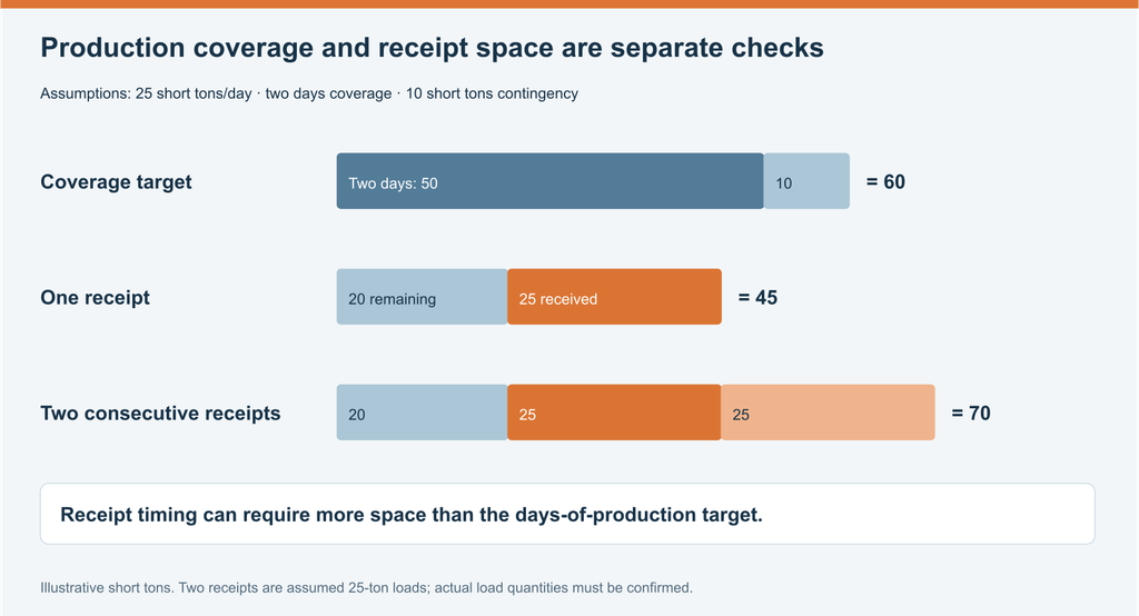
Return to the 25-short-ton-per-day example. Two days of production plus a separately chosen 10-short-ton contingency creates a 60-short-ton inventory target:
Coverage target = 25 × 2 + 10 = 60 short tons
Now consider a hypothetical 25-short-ton delivery arriving with 20 short tons still in storage. Immediately after receipt, inventory is 45 short tons. A usable storage limit of 60 would accommodate that event, leaving 15 short tons below the limit.
The result changes if two such deliveries arrive consecutively before meaningful drawdown. Together they add 50 short tons to the 20 remaining, taking inventory to 70. That receipt pattern needs more space than the two-day coverage target. The individual 25-short-ton loads are assumptions to agree with the supplier and carrier, not a claim about typical or legally permitted truck loads.
| Planning condition | Arithmetic | Storage implication |
| Two-day coverage with contingency | 25 × 2 + 10 | 60 short tons of usable stock |
| One assumed delivery arrives | 20 remaining + 25 | 45 short tons after receipt |
| Two assumed deliveries arrive before drawdown | 20 + 25 + 25 | 70 short tons after receipt |
| Two-day coverage and consecutive receipts both required | Larger of 60 and 70 | 70 short tons of usable storage in this scenario |
The point is not that this plant automatically needs a larger silo. It needs a storage plan and a delivery schedule that agree. The supplier might be able to spread the two receipts across production, change a load quantity, or reserve a different delivery window. The available options depend on actual supply arrangements and the plant’s tolerance for disruption.
Test a busy week before selecting the final capacity
A short inventory schedule reveals peaks that a days-of-storage calculation can miss. The next table starts with 70 short tons and assumes deliveries occur before that day’s production. The Thursday receipt consists of two assumed 25-short-ton deliveries. All quantities are hypothetical and in short tons.
| Day | Opening inventory | Receipts before production | Inventory after receipts | Cement consumed | Closing inventory |
| Monday | 70 | 0 | 70 | 20 | 50 |
| Tuesday | 50 | 25 | 75 | 25 | 50 |
| Wednesday | 50 | 0 | 50 | 35 | 15 |
| Thursday | 15 | 50 | 65 | 30 | 35 |
| Friday | 35 | 0 | 35 | 20 | 15 |
The weekly mass balance is consistent: 70 opening plus 75 received minus 130 consumed leaves 15. Yet the plan exceeds a 70-short-ton usable limit on Tuesday, when receipt takes stock to 75. Total weekly consumption and final inventory look reasonable; the arrival-time peak makes the plan incompatible with that limit.
Moving Tuesday’s delivery later, after at least five short tons of drawdown, could remove that particular peak. The revised schedule still needs a shortage check. If Thursday’s receipts slip until after production, Wednesday closes with 15 while Thursday requires 30. Another 15 short tons would be needed to complete that day, even before considering the chosen contingency.
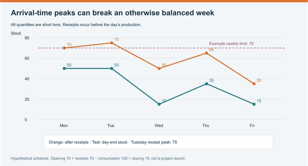
The illustration is a worksheet for actual production and delivery inputs. Where filling and consumption overlap, shorter time intervals show how the inventory peak changes. The installed system determines whether simultaneous receipt and production are permitted.
Set a reorder trigger that includes lead time
A starting reorder calculation is expected consumption during order-to-arrival lead time plus a justified contingency. At 25 short tons/day and a hypothetical one-day lead time, retaining 10 as contingency suggests a trigger of 35 short tons. Reaching that trigger prompts an order; it does not by itself prove the arriving load will fit.
With no other receipt or consumption change, inventory would fall from 35 to about 10 before arrival. An assumed 25-short-ton receipt would then raise it to 35. That schedule is quite different from accepting two deliveries while 20 remain. The same equipment can behave differently under different ordering policies.
Where orders are already in transit, use projected stock at each arrival rather than placing duplicate orders from the displayed inventory alone. Record the committed receipt time, quantity, and expected demand before arrival. An early truck can create a space conflict, while a late truck can create a shortage. Both outcomes belong in the same plan.
Contingency is a business and operating choice supported by demand variation, delivery reliability, and the consequences of interruption. A blanket “three days” or “20% extra” rule cannot account for all sites. Model the specific delay or demand change the extra stock is intended to cover, then agree the resulting plan with the supply and production teams.
Storage capacity and feeding capacity are different
Storage capacity answers how much usable stock can be retained. Feeding capacity answers how quickly material reaches the production receiver. A large vessel can still feed a plant too slowly if the outlet, conveyor or receiving sequence limits transfer.
For batch production, the available fill window determines the required average transfer. An assumed 1,000 lb cement charge delivered in 90 seconds requires about 667 lb/min; the same charge in 60 seconds requires 1,000 lb/min, and in 30 seconds requires 2,000 lb/min. The arithmetic describes demand, not the performance of a particular auger.
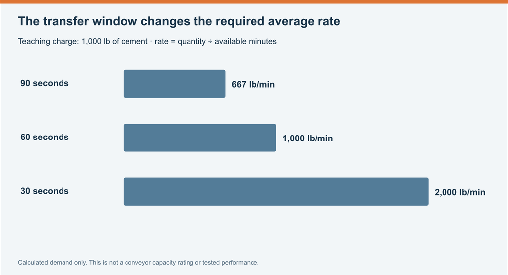
A faster catalog rate has little value if the receiving hopper cannot accommodate the charge or the production sequence does not allow that transfer. Similarly, adding silo volume does not change the rate of an unchanged outlet and conveyor. Storage and feeding should be matched to the same production scenario while retaining their separate functions.
Reconcile mass, usable volume and allowable load
A ton measures mass; cubic feet measure volume. A stated mass capacity depends on the bulk density and filling condition used in the rating. Pneumatically delivered powder contains air, so settled-material density may not represent its volume during receipt.
Zimmerman’s sizing guide defines a barrel as 4 ft³ and gives 300 lb for blown-in cement per barrel. Those values imply 75 lb/ft³ under that supplier’s convention. They show why a barrel label needs a density basis; they do not establish a universal cement density for all equipment.
To illustrate the volume requirement, assess 70 short tons at 75 lb/ft³ and assume usable material space occupies 85% of geometric volume:
Illustrative geometric volume = 70 × 2,000 ÷ (75 × 0.85) ≈ 2,196 ft³
The 85% figure is an arbitrary example input, not a recommended filling limit. Usable volume, structural load limits and the permitted filling condition belong to the selected model’s rating. The calculation estimates space; it does not establish that rating.
Density sensitivity is worth checking because it changes the space requirement without changing the required mass. Under the same arbitrary 85% assumption, a hypothetical 65 lb/ft³ gives about 2,534 ft³, while 85 lb/ft³ gives about 1,938 ft³. These are sensitivity inputs, not a published cement-density range. They illustrate why an optimistic assumed density can make a vessel appear large enough on paper.
Label units in every inquiry. A short ton equals 2,000 lb, approximately 907.185 kg, while a metric ton equals 1,000 kg. The example’s 70 short tons are about 63.50 metric tons. NIST’s conversion factors establish that distinction. “70 tons” without a unit convention leaves the intended duty unclear.
Keep the three capacities separate when comparing a proposal: geometric vessel volume, usable material capacity under the specified conditions, and maximum permitted load. Also identify stock that the operating plan excludes because it is not readily available to production. The quotation should explain the relationship rather than provide one unqualified number.
The cement silo capacity planning guide continues the calculation task. For the final model, request the manufacturer’s capacity basis and check it against both the busy-week schedule and the proposed receipt conditions. A cement silo capacity calculator helps evaluate stated assumptions; the drawings and operating limits settle the equipment choice.
How Much Does Cement Silo Costs?
Cement silo price varies because the quoted object varies. A vessel-only offer, a complete storage-and-discharge package and an installed system include different work. Even at the same nominal capacity, construction, accessories, shipping arrangement and site requirements can change the total substantially.
Capacity, geometry and structural specification
Increasing storage generally increases the amount of enclosure, support structure and other equipment needed, but price does not rise in a simple fixed amount per ton. Two capacities may share some accessories while requiring different shell dimensions or supports. Conversely, two vessels with the same mass label may have different usable volumes or material-density assumptions.
The project’s structural basis can also change the design. Support height, openings, environmental loads and the operating arrangement affect what has to be engineered and fabricated. Plate thickness cannot be judged independently of geometry and design loads. A heavier vessel is not automatically better, and a lighter one is not automatically cheaper to install safely.
Shell material, surface preparation and coating specifications add another cost dimension. A quoted finish should describe the intended protection rather than rely on adjectives such as “heavy duty” or “corrosion resistant.” The relevant question is what preparation and coating system is included for the actual environment and maintenance plan.
Welded versus bolted cost
Factory labor, joint components, shipped volume and destination labor contribute differently to welded and bolted proposals. The modular connection and sealing system can add manufacturing items while reducing shipping difficulty. Whether that combination lowers the project cost depends on the actual route and assembly scope.
Transport can reverse the equipment-price comparison. An assembled welded vessel can be awkward or expensive to ship when its dimensions control the route. A modular package may fit a more manageable shipping arrangement but creates labor, lifting and inspection work at the destination. The total depends on both ends of the journey.
An accessible local delivery route and limited assembly resources can favor factory assembly. A long-distance shipment with competent destination assembly support can favor a modular option. Neither scenario establishes a universal percentage saving.
Accessories and process integration
Filters, protection components, flow aids, conveyors, weighing equipment and controls are functional parts of the supply system. Omitting them can reduce the equipment line while leaving a plant that cannot receive or supply cement as intended. Their specifications can therefore change cost as much as the shell choice.
A longer or differently routed conveyor may need a different configuration from a short transfer connection. A receiver with weighing and venting requirements adds scope beyond storage. Control integration can range from defined local functions to coordination with an existing plant sequence. Those are different deliverables, even when the sales description is “cement silo with accessories.”
Service access and documentation have practical value too. Platforms, component-removal space, manuals, identified parts and agreed acceptance records influence installation and later use. They should be associated with the work they enable, rather than treated as unexplained optional extras.
Published prices and the limits of a quote range
Published figures can provide context, but only when their date, equipment and scope remain attached. The following examples were reviewed on October 4, 2026. They are supplier or seller statements, not a survey of comparable installed systems.
| Published example | Stated figure | What the figure represents |
| eQUIP’s guide, published February 20, 2025 | €13,000–€16,000 for a 100-ton welded silo; €15,000–€18,000 for a 100-ton bolted silo | Supplier-reported 2025 ranges; unit convention and project inclusions require confirmation |
| WM machinery’s WM-CS50 page | US$7,600 | Displayed product price; page marked Sold out and shipping calculated separately |
| eBay’s custom 50-ton used silo listing | US$8,500 asking price | A used equipment listing with freight to be arranged; condition and included scope differ from a new package |
These examples do not form a single “cement silo market range.” A dated supplier estimate, a product-page price and a used asking price answer different questions. Currency conversion would not remove the differences in size, condition, accessories, delivery or site work.
A useful quotation range must describe the configuration and inclusions. For preliminary budgeting, a supplier can quote alternatives for a defined duty: for example, two construction methods with the same usable capacity and receiving system. The range then represents stated options, rather than a low and high number collected from unrelated pages.
Transport, assembly and the installed total
Shipping cost depends on packed dimensions, weight, handling method, route and destination. An assembled vessel’s cargo envelope may be decisive. Modular crates, panels, supports and accessories still need an agreed packing list and handling arrangement. “Fits in a container” is a proposed packing result to verify, not a feature that applies to every bolted model.
Transport continues beyond ocean freight or the dispatch point. Destination handling, local delivery, unloading and any route requirements can create separate costs. Trade terms and the named location establish commercial responsibilities, but the project still needs to assign the physical work required to bring the equipment into operation.
Site assembly and foundations are also separate from shipping. A bolted package may need erection labor and joint inspection, while an assembled unit may require different lifting resources. Both need the model’s support arrangement, utilities and plant interfaces. Those tasks explain why a low equipment price can lead to a larger project total.
The cement silo cost guide develops the budget categories. An itemized project proposal should connect each cost to the equipment or work it provides.
A scope-normalized quotation example
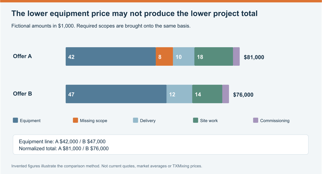
The following fictional worksheet shows the method. Offer A has an equipment line of $42,000 and includes a specified filter and instruments, but excludes the conveyor. Offer B starts at $47,000 and includes the conveyor as well. All amounts below are invented for illustration, not supplier quotations or market estimates.
| Required scope | Fictional offer A | Fictional offer B |
| Equipment package described above | $42,000 | $47,000 |
| Missing conveyor and connection work | $8,000 | Included |
| Delivery allowance | $10,000 | $12,000 |
| Site-work allowance | $18,000 | $14,000 |
| Commissioning allowance | $3,000 | $3,000 |
| Demonstration total | $81,000 | $76,000 |
Offer A starts $5,000 lower on equipment but ends $5,000 higher under these stated assumptions. The result shows why required scope matters; it does not show that a higher purchase price is always better. Real proposals also need consistent tax treatment, quantities, trade terms and acceptance requirements.
Ownership, rental and used equipment
Operating cost includes the actual energy used, routine maintenance, consumables and support arrangements. Motor nameplate power is not a measured energy bill; equipment runtime and operating conditions matter. Filter elements, seals and other service items need identifiable replacement specifications so that a future quotation relates to the installed equipment.
Rental may suit a defined project period where suitable equipment and service terms are available. Purchase may suit repeated use across projects or a long operating life. The financial comparison includes mobilization, removal, maintenance responsibility, extensions and a defensible residual-value assumption. There is no universal month at which one becomes preferable.
Used equipment can reduce the purchase line but introduces uncertainty about condition, configuration and restoration work. Removal, transport, replacement protection components, electrical adaptation or missing documents may add scope. The relevant total is the cost of an acceptable installation for the proposed duty, not the seller’s asking price alone.
Tips on Installation, Maintenance and Selection Cement Silo System
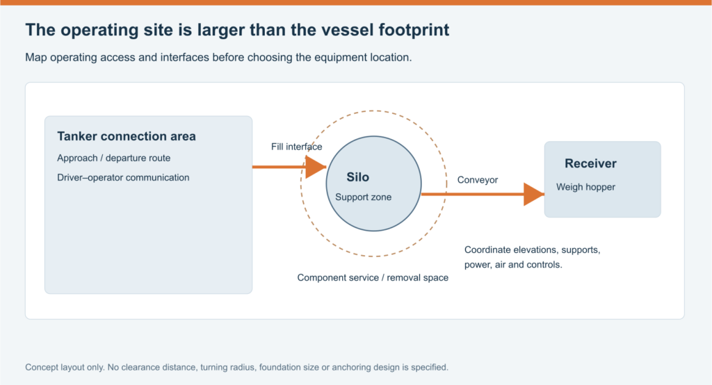
Installation turns the supplied configuration into the operating material route. The vessel, supports, fill connection, filter, discharge assembly, conveyor and receiver need to connect at the intended positions. The layout should make normal deliveries, production and later service practical without placing conflicting tasks in the same space.
The foundation or operating support is designed for the model and site. Equipment and material loads, support reactions and applicable environmental conditions are part of that design. A standard slab thickness inferred only from nominal tonnage cannot establish a suitable installation. TXMixing’s dimensions and foundation guide provides further planning context; the project documents establish the actual requirements.
Utility compatibility is part of the equipment arrangement. Motors and controls need the appropriate electrical supply, while components using compressed air have their own pressure, quality and consumption requirements. A package that arrives with incompatible utilities may be physically complete but unable to perform its intended function.
Commissioning establishes the installed configuration and its response under the agreed conditions. Relevant records can include assembly inspection, instrument verification, demonstrated protection responses and a transfer test with the material and route stated. These records connect the delivered equipment to the duty that was purchased.
Routine maintenance keeps the material, air and control paths available. Filter condition affects venting; outlet and conveyor condition affect transfer; measurement condition affects stock and batch information. Changes in one path should be investigated in that context rather than treated as evidence that the entire silo needs replacement.
Stock indicated in the vessel with little material entering the weigh hopper can point to an inventory, outlet, conveying or measurement problem. Powder escaping during receipt points toward a different part of the system. Recording the material, operating state and alarms helps maintenance distinguish the event. The bulk cement silo troubleshooting guide continues that task at a general level.
Maintenance should relate visible changes to the function affected. Powder escaping during filling calls attention to containment and filtration. A changing transfer time for the same batch charge calls attention to the feeding route and receiver. Unexpected stock differences call attention to delivery records, material use and measurement. These observations identify an investigation path; they do not establish a fault by themselves.
Service planning includes filter elements and cleaning equipment, conveyor bearings and drive components, enclosure seals, instruments and the supporting structure. The manufacturer’s intervals and procedures govern the work. Keeping a record of operating hours, alarms, replacements and material changes makes recurring problems easier to distinguish from one-off delivery events. Access and replacement-part availability matter because maintenance has to be practical at the installed location, not merely possible on a drawing.
Cement silo cleaning and internal inspection are specialized maintenance activities. Entry, clearing material and work on energized or pressurized equipment require the applicable authorized process. OSHA’s general-industry confined-space standard and construction confined-space scope illustrate why the work setting and hazards must be assessed separately from ordinary operation. Requirements depend on the project’s jurisdiction and activity.
A complete selection now has a clear sequence. The application identifies the powder and receiving process. The type determines the storage and deployment arrangement. Sizing relates usable stock to production and receipts. The component package completes the material, air and control routes. Transport and installation determine whether the proposed configuration can reach the site and operate there, while scope makes its price comparable.
A useful quotation brief includes the material, expected and busy-period production, delivery quantities and timing, usable storage target, available space, receiving position and utilities. The supplier’s response should identify the proposed configuration, capacity basis, included equipment, drawings, delivery and installation responsibilities, and support terms. This is enough to begin a technical discussion without turning the inquiry into a list of every accessory in a catalog.
When comparing a cement silo configuration from TXMixing, connect those inputs with the proposed model and package. You can send the storage and production requirements together with a layout and intended delivery location. The resulting offer should explain how the selected system supplies the process and which work remains outside the quoted scope.
Cement Silo FAQs
What is a cement silo used for?
A cement silo stores dry cement powder and supplies it to batching, mixing or transfer equipment. It buffers production between deliveries. It normally holds a concrete ingredient, rather than fresh concrete.
Can the same silo store cement and fly ash?
A silo may be configured for either material when its design, filtration and discharge equipment suit the duty. Recipes requiring both materials need separate storage and identified routes. A capacity rated for cement does not automatically give the same usable mass capacity for fly ash.
Is a bolted silo better than a welded silo?
The better choice depends on the project. Bolted construction can reduce the shipping envelope but adds site assembly and joint inspection. Factory-assembled welded equipment can reduce shell-assembly work when the delivery route and lifting arrangements accommodate it. Compare the complete delivered and installed scope.
Does low profile mean portable?
No. Low profile describes height, while portable describes relocation. A low-profile silo can be fixed or relocatable; a portable silo can be upright or low profile. The model determines its move procedure and permitted transport condition.
Can a mobile cement silo travel while full?
Only if its documented transport rating permits it. Wheels or a trailer do not establish a loaded-movement rating. Some portable models must be emptied before lowering and transport; the selected equipment’s instructions settle the question.
How much cement storage does a plant need?
Enough usable stock for the planned production and supply interval, plus enough free space for scheduled receipts. Model busy-period consumption and inventory at each arrival. Nominal tonnage alone does not establish usable capacity, and storage volume does not determine the conveyor’s feed rate.
What should a cement silo quotation include?
It should identify the capacity basis, vessel construction, filter and protection equipment, discharge system, controls and interfaces. Transport, unloading, supports or foundations, assembly and commissioning need explicit responsibility and inclusion statements. Compare these items before comparing the equipment price.
Conclusion
A cement silo works well when its storage, material flow and plant layout serve the same production duty. Start with the powder and receiving process, then choose the orientation, construction and deployment arrangement. Match usable capacity to consumption and deliveries, and evaluate the complete equipment, transport and installation scope together.
For a TXMixing proposal, review the cement silo range and modular cement silo information. Send the material, production demand, delivery schedule, available space and receiving position through the TXMixing inquiry page. Those inputs give the supplier a clear basis for proposing a configuration and explaining what the quotation includes.
![17586798369ba58b[1]](https://txmixing.com/wp-content/uploads/2026/02/17586798369ba58b1.jpg)